Getting Started with the MKR RGB Shield
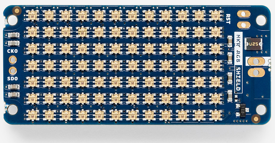
This shield has been designed as a multipurpose RGB pixel based display. The design of the MKR RGB Shield allows it to be mounted as the last one in a stack or the only shield mounted. It has a matrix of 84 APA102 RGB Smart LEDs organized in 12 columns and 7 lines. Each LED has a footprint of 2x2 mm and the overall size of the matrix is 36 x 21 mm.
Thanks to these hardware characteristics the matrix is suitable for graphics, icons or scrolling text messages. Each pixel can be lit with a color selected from a palette of 16 millions.
Software
To let you take advantage of the matrix, we have developed a library - Arduino_MKRRGB - that interfaces the hardware with our new high level graphics library ArduinoGraphics. With these two libraries you can quickly create visual content with little effort. The arrangement of the LEDs is by lines starting from top and going down always starting from the left
Please refer to the Arduino_MKRRGB Library reference for a detailed description of the available commands related to the MKR RGB Shield and to the ArduinoGraphics Library Reference for a detailed description of the graphics primitives available.
These libraries are available as usual through the Library manager. Search for Arduino_MKRRGB and for ArduinoGraphics in the search field.
Hardware
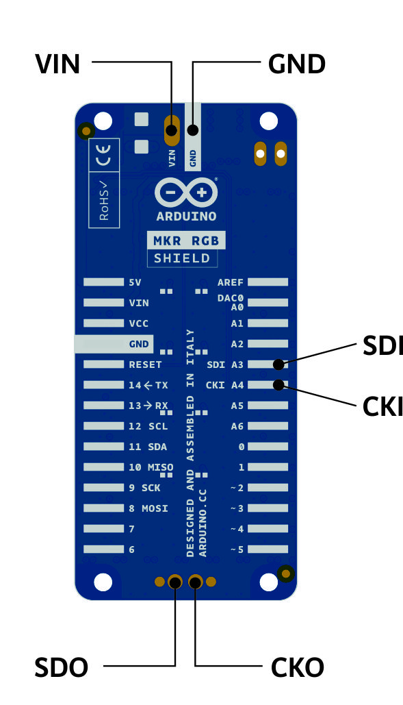
The 84 APA 102 LEDs are connected in series: you drive just the first one and all the others receive the commands one after the other one. The interface is an SPI like one, with CLK and DataIn pins connected to A4 and A3. Our Arduino_MKRRGB library already takes care of it, but you can use any other SmartLED library just defining the CLK and DATA pins on A4 and A3.
As you may know, each LED RGB SMD chip can draw up to 40 mA. If we multiply the maximum current by the number of LEDs we get to close to 4A. This is the peak current with all the LEDS set to white and full brightness. Nothing that the MKR regulator or a standard PC USB port can support, therefore the shield has a separate power supply connector, capable of handling up to 4A. Please connect a proper 5V power supply to the shield if you plan to create dense graphics at high brightness.
The shield has two output pads to cascade another shield or other APA102 LEDs arranged as strip. Our library will take care of just one matrix, for cascaded and more complex designs you should use other libraries.. The output from the first shield pads named CKO and SDO should go to the A4 and A3 pins of the headers of the next MKR RGB Shield. Power supply should be provided with a common ground for all the power supplies connected to the MKR board, the first shield and the other cascaded ones.
Example
This sketch demonstrates how to display and scroll text on the MKR RGB Shield. It continuously scrolls the current millis() value on the display.
MKR RGB - Scroll Text
This example demonstrates how to display and scroll text
on the MKR RGB shield. It continuously scrolls the
current millis() value on the display.
The circuit:
- Arduino MKR board
- Arduino MKR RGB shield attached
This example code is in the public domain.
*/
#include <ArduinoGraphics.h> // Arduino_MKRRGB depends on ArduinoGraphics
#include <Arduino_MKRRGB.h>
void setup() {
// initialize the display
MATRIX.begin();
// set the brightness, supported values are 0 - 255
MATRIX.brightness(10);
// configure the text scroll speed
MATRIX.textScrollSpeed(125);
// display some short text without scrolling
MATRIX.beginText(0, 0, 127, 0, 0); // X, Y, then R, G, B
MATRIX.print("Hi");
MATRIX.endText();
delay(2000);
}
void loop() {
MATRIX.beginText(MATRIX.width() - 1, 0); // use the same color as before, start text at the right edge
MATRIX.print("millis=");
MATRIX.println(millis());
MATRIX.endText(SCROLL_LEFT); // SCROLL_LEFT parameter here to configure scrolling left
}
Last revsion 2019/03/22 by SM
The text of the Arduino getting started guide is licensed under a Creative Commons Attribution-ShareAlike 3.0 License. Code samples in the guide are released into the public domain.
